

Learn Plc Programming
PLC Zero, the smallest CPU module in the Fulmatic 7 PLC family. You can use PLC programming to learn. You can use all the features of Fulmatic 7 PLCs without any restrictions. You can use Fulmatic SOFT program without license requirement. It is possible that the device has no protection and can be disrupted due to user error. Therefore, it is sold without warranty. We are 100% tested to ensure that no grievances occur, and we ensure that all functions are functioning.
STM32 PLC Development Board
When you purchase PLC Zero, it comes with Fulmatic SOFT firmware pre-installed. However, you are not obligated to use it as a PLC, you can also use it as an STM32 development kit. Please note that the product comes with the firmware installed by us when you receive it. If you decide to change the firmware, there is no going back. You can download the firmware we prepared for STM32F407VGT6 from our website and use it again as a PLC. However, if you change the firmware, you won’t be able to write PLC code larger than 2 KB. In contrast, the initially delivered firmware allows you to write up to 115 KB of PLC code.
You can write your own chip code using the Fulmatic Core library and program it with Fulmatic SOFT. You can see an example project written for the STM32F407VGTx in our Github repository. https://github.com/FultekPLC/Plc-Firmware Click here for our PLC Firmware library.
You can download Fulmatic SOFT Firmware in here.
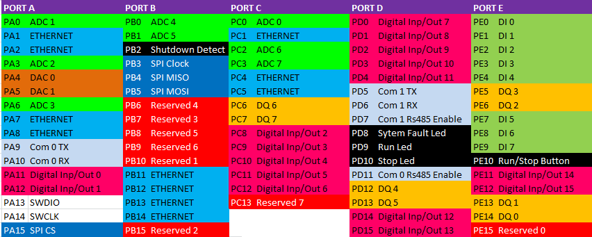
Click here for PLC ZERO circuit diagram. Click here for PLC Zero dimension.
General Features
- All inputs and outputs are 3.3 V and unprotected. Read STM32F407 datasheet for pin currents and other information.
- PLC Zero’s power supply is usb. It can also be supplied with 5v or 3.3v via pins.
- PLC Zero has 42 Input / Output channels.
- PLC Zero has 8 x 200 KHz Digital input. There are 3 buttons (I 0.0-I 0.2) for simulation.
- PLC Zero has 8 x 655KHz Dijital output. There are 3 LEDs for simulation (Q 0.0-Q0.2) .
- PLC Zero has 8 x 12 Bit Analog input. There are 1 trimpot (AI 0) for simulation.
- PLC Zero has 2 x 12 Bit Analog output.
- Also, PLC Zero has 16 x Configurable Digital input and output.
- PLC Zero has power LEDs, plc run and plc stop LEDs.
- 10/100 mbit full duplex ethernet.
- There are 2 Rs485 or Rs232. But you have to make the transceiver circuit.
PLC Features when Used as PLC
– 115 KB. programming memory,
– 1 x 10/100 mbit full duplex ethernet
– Modbus TCP/IP,
– Web server with 512KB file space ,
– 2 x serial port (Modbus RTU)
– 8 x 200 KHz. digital input and 8 x 655 KHz. digital output,
– 8 x 12 Bit Analog input,
– 2 x Analog output,
– 16 x Configurable Digital input and output .
Practical Information
- PLC Zero with no protection can be disrupted by static electricity.
Don’t touch the bare hand pins or pcb, even if it is energized or de-energized. - Your PLC code or values of the Datablock you load will be reset when the PLC power is switched off. Because, the SD Detect pin that detects that the PLC is de-energized is not connected. You can connect SD Detect pin with gnd for manual recording. SD Detect pin is J2 30 .
- When you want to make your own PLC with PLC Zero, the J1 and J2 headers may need to be inserted into the back of the card. If you specify in your order we can send the bottom materials without soldering.
- USB connection is only used for power. It does not support other usb functions.
- PLC Zero has a real-time clock (RTC) but no battery. You must remove the R13 resistance when you want to install a battery. You can connect the 3.2v battery to pin J2 24.
- Chip analog input is made with 3.3v. Disconnect the resistance R15 for a different analogue supply. You can supply the analog supply voltage from the pin J2 22.
- If more than one PLC Zero connection will be made to the same network, the MAC addresses of PLC Zero’s must be changed. To do this, go online with the PLC and change the last byte of MAC address in DB0. Go offline. Change the IP address in the PLC hardware settings and upload it to the PLC. To make these settings permanent, connect J2 30 SD detec pin with gnd and PLC will go to stop. Then cut the energy and give it back.
Communication PLC
PLC Zero comes with a default IP address of 192.168.0.10. To establish a stable communication with the device, please follow the steps below:
1. Direct Connection (PC to PLC)
You can connect the PLC Zero directly to your computer without using a switch. In this case, you must set your computer’s IP address so that the first three bytes are the same (192.168.0.XXX) and the last byte is different (any number other than 10).
2. Connection via Switch
You can also connect to the PLC Zero through a network switch:
- If your network structure is compatible: If your existing network’s first three bytes are the same as the PLC Zero (192.168.0.XXX), you can connect directly. Ensure there are no IP conflicts on the network.
- If your network structure is different: If your local network is on a different IP block, you can access the PLC Zero via a switch by temporarily changing your computer’s IP address to the 192.168.0.XXX block.
3. Changing the IP Address and Permanent Saving
If you wish to change the PLC Zero’s IP address to match your own network:
- To perform a manual save, simply short-circuit the SD Detect pin (Pin 30 on the J2 socket) to GND.
- Define the new IP address in the hardware settings within the Fulmatic SOFT software.
- Upload the prepared hardware settings to the PLC Zero.
- Important: PLC Zero does not automatically save settings when the power is disconnected. To make IP and hardware changes permanent, you must perform a manual save.
Change TCP/IP settings for PC
1-Select Start, then choose Settings > Network & Internet
2-Select Ethernet, then select Change adapter options for the Ethernet network you are connected to.
3-Right-click on the connected network and choose Properties.
4-While Internet Protocol Version 4 (TCP/IPv4) is selected, choose Properties.
5-Enter the IP address and Subnet mask sections, then select OK to save your settings.


