
Our Objective: This library has been developed to enable you to design and build your own PLC. Our goal is to build an ecosystem of devices programmable via Fulmatic SOFT, where your control over the hardware is maximized. You can utilize this extensive library with your preferred chip and IDE. Furthermore, you have full autonomy to define your own circuit schematics and all other hardware specifications.
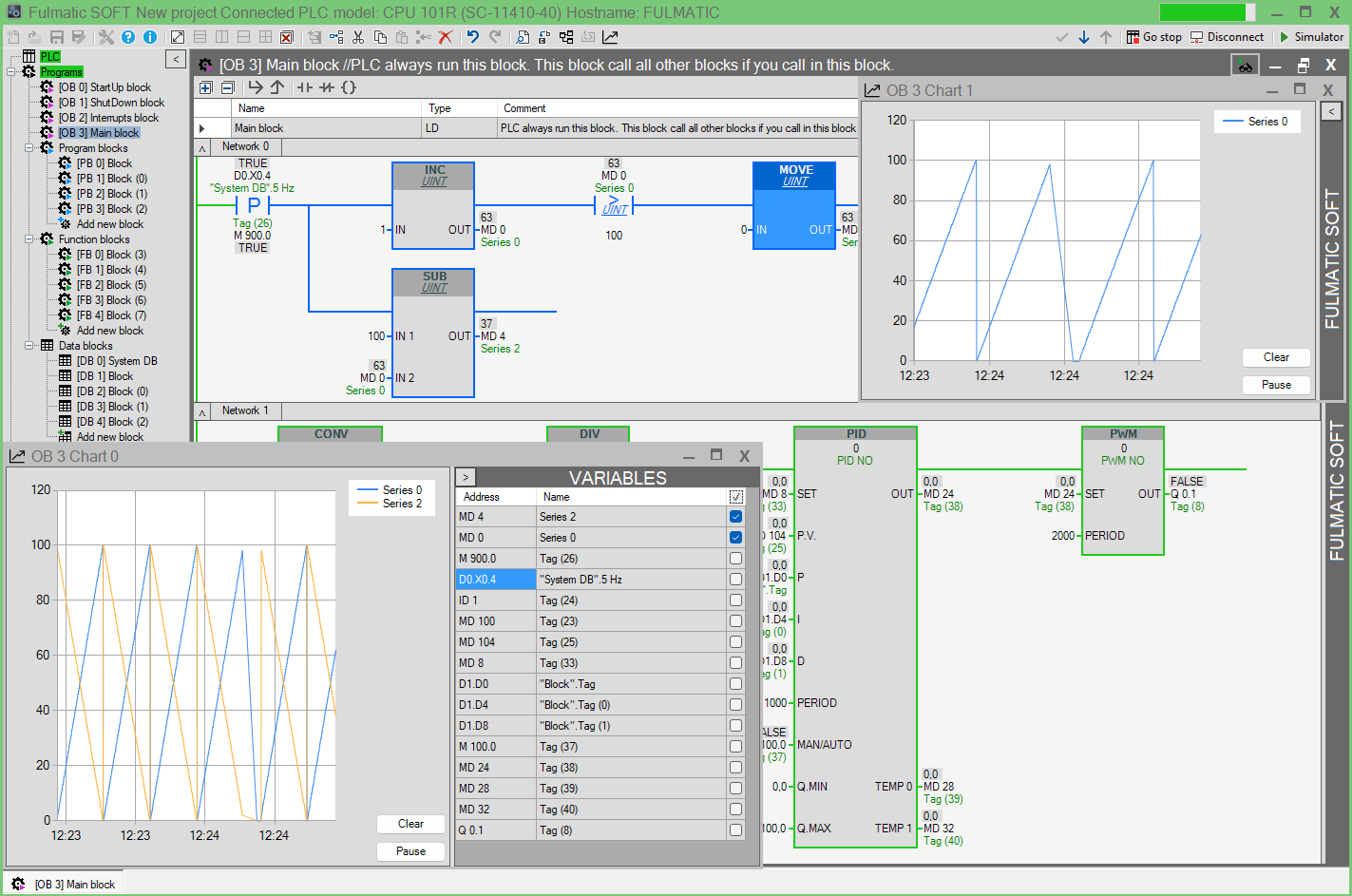
Fulmatic SOFT: By integrating the Fulmatic Core library into your chip code according to the provided instructions, you can program your embedded systems in Ladder Logic (IEC 61131-3) using Fulmatic SOFT. Beyond the standard features of modern PLCs, Fulmatic SOFT offers enhanced capabilities including TCP, UDP, Motion Control, and SD Card commands. It provides a vast programming area with 772 blocks (256 DB, 256 PB, 256 FB, and 4 OB) and supports up to 16,384 I/O points.
Free PLC Firmware: You may use the PLC library free of charge for up to 2048 bytes (1026 bytes are used by DB0). For applications requiring larger memory, a license must be purchased for $10 USD. Without a license, the PLC operates for 60 minutes per session. Our transparent licensing model involves no complex contracts or bureaucratic processes. To implement the licensing system, a TSHA204A-SSHDA chip must be integrated into your circuit. Upon purchase, you will receive a license key. The License Application uses this key to connect to our server and uploads the license code to your chip via serial port or Ethernet, automatically updating your license count on the server.
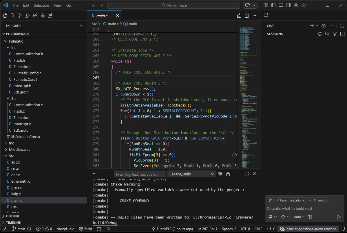
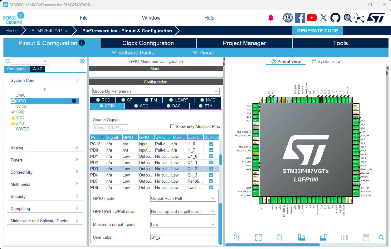
Github: To evaluate the PLC library, you can download our sample project—configured for the STM32F407VGTx using VS Code—from GitHub: https://github.com/FultekPLC/Plc-Firmware
This project features a fully functional, open-source PLC firmware that utilizes nearly all of the chip’s native capabilities. You can modify hardware configurations using CubeMX and proceed with development seamlessly within the same project. VS Code allows you to adjust both hardware settings and firmware logic. Additionally, you can integrate custom functions into the PLC firmware and execute them directly within the PLC code. The library supports any brand and model of ARM chips, allowing you to define your own I/O count and types without restrictions, provided you comply with the licensing terms.
Firmware Updates: End-users of your product can perform PLC firmware updates directly through Fulmatic SOFT. The PLC firmware update code is entirely open-source; you can review and modify the bootloader code within the sample project. While we provide a proven bootloader structure, you are free to develop and implement your own custom solution.
Code Guide
We are committed to making our 200 KB sample project as accessible as possible. For a single chip, a 200 KB codebase represents a significant project; we acknowledge that understanding, modifying, and implementing a project of this scale can be challenging. To assist you, we have provided detailed function descriptions within this page and throughout the source code. We are continuously working to improve our documentation.
While we strive to answer your questions through the Discussions section of our GitHub repository. Please note that we do not provide free technical support for Fulmatic Core. If you require professional assistance, including custom circuit board design and full-scale implementation, please contact us for a formal proposal.
You can download the sample project from our GitHub repository: https://github.com/FultekPLC/Plc-Firmware. This repository allows you to examine and modify all PLC features in an open-source environment. You are free to remove unnecessary functions or integrate new features as needed.
Information regarding IDEs and compilation tools is available on GitHub. Below, we outline the primary functions used for integrating the library with your MCU code.
FulmaticConfig.h
This file is used to define the firmware version and various string size parameters.
FulmaticCore.h
This header file contains the prototypes for the functions you will call from your MCU code. Detailed explanations for each function are included within the file. The library operates using numerous variables and arrays; you must initialize these within your MCU code. The Variables_TypeDef structure is used to pass these variables to the library and its structure must not be modified.
FulmaticExecute: This is the primary function called within main.c to execute the PLC Ladder logic. It is triggered during the Startup block (as the PLC enters Run mode), the Main block (every cycle), the Shutdown block (when the PLC stops), and via Interrupt.c for digital input interrupts or Fulmatic.c for time-based (Timer) interrupts.
FulmaticInit: This function must be executed only once during the initial chip boot sequence. A return value of 1 indicates that the license chip has been successfully authenticated and the system is operating in licensed mode.
Fulmatic.c
All essential functions required to utilize the library within your code are consolidated in Fulmatic.c. This file serves as the central hub branching out to other modules. The functions are categorized into four main groups:
- Functions required for the sample project but not utilized by the core library.
- Mandatory functions required by the library within your code.
- Licensing functions (optional for unlicensed operation).
- Conditional functions based on utilized PLC commands (e.g., TCP, UDP, SPI, Serial, and SD Card functions can be omitted if not required).
_DefaultEprom: Hardware settings selectable via Fulmatic SOFT are stored in PlcSetupEprom[STPMEMORYSIZE], while ladder codes are stored in PlcEprom[PRGMEMORYSIZE]. The _DefaultEprom function contains the PLC’s default configuration, which you can customize within these arrays.
_EachMilliSecond: Executed every millisecond, this function is called from both the main loop and the library. In the sample project, it is managed via flags within the TIM7_IRQHandler in Interrupt.c, rather than being executed directly. Additionally, the TIM7->ARR value is calibrated via RTC. Please review the _RtcCalibration function in Fulmatic.c; inaccurate calibration will result in minor timing errors across all time-based PLC operations.
_DelayUs: This may require adjustment based on your chip’s clock frequency. We recommend testing and calibrating over an extended period for precision. It is currently calibrated for 168 MHz.
_SetOutputs: Under normal operation, I/O processing occurs within main.c. However, when time-based or digital input interrupts are triggered, the OB2 interrupt block is executed. This function is called from within the library to set outputs without latency.
_GetMsTimerCount: Essential for duration measurements in various operations. This must be included in your code to provide the current value of the one-millisecond timer.
_CrcCalculate: Utilized for hardware-based checksum calculations. Ensure this is correctly implemented for your specific MCU.
Communication.c
This file contains the necessary logic for Ethernet, Serial Port, and SPI integration within the PLC. Modbus requests and calls from Fulmatic SOFT are processed here. To ensure data integrity, responses are initiated with a slight delay from within main.c. This module also includes open-source code for firmware updates and SD card operations. You may modify these codes to replace Fulmatic SOFT with your own custom software.
Flash.c
PLC code and persistent timer-counter data are saved to Flash memory during power loss and restored upon reboot. Ensure that the sector information in Flash.h is correctly configured for the specific chip you are using. To detect power failure, you can utilize the following circuit:
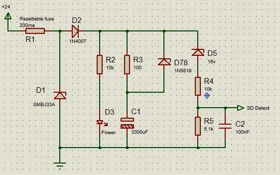
This circuit triggers the Shutdown Detect pin to low when the 24V supply drops to approximately 19V. The C1 capacitor ensures the chip remains powered for a short duration. Since erasing and re-writing to Flash during this critical window is risky, the following protocol must be implemented:
- Data from Sector 10 is copied to Sector 11. This ensures that if power fails during the boot process, a valid data set remains safely stored in Sector 11.
- o save new data to Flash, the sector must first be erased—a process significantly slower than writing. Therefore, Sector 10 is erased during startup to prepare for an eventual shutdown.
- The detection circuit provides a buffer of slightly more than 1 second. Upon detection, data is written to Sector 10 within 100-200 ms. Since the OB1 Shutdown Block executes before closing and the PLC may contain extensive ladder logic, the C1 capacitor must be at least 2200 µF. A 100-ohm resistor is included as a current limiter to prevent inrush current shocks to the circuit.
- During the boot sequence, the system reads all data from Sector 10 and performs a checksum. If power was lost during a previous write, the checksum will fail. In this case, there is no need for concern; the system will automatically restore and boot from the valid data in Sector 11.
Interrupt.c
This file contains the interrupts for Digital Inputs, ADC, Timers, and UART. These are enabled or disabled within the _INTSetup function in Fulmatic.c based on the PLC’s operating mode. Ensure _INTSetup is tailored to your specific hardware.
The functions in this file must execute with high efficiency. While our example code uses switch statements for readability, there are faster methods available. For instance, operations within a switch can be written as individual functions:
void Handle_Encoder(void)void (*EXTI0_Handler_Ptr)(void);- In
INTSetup(based on Fulmatic SOFT selection):EXTI0_Handler_Ptr = Handle_Encoder; - Upon interrupt: Execute
EXTI0_Handler_Ptr();withinEXTI0_IRQHandler.
Another optimization involves Byte to 32-bit conversions. For the STM series, you may use the following: (int32_t *)&PlcIO[EncIAdr[0]] = __rev(ValueS32);
Important Note: Do not use the HAL library for clearing interrupt flags; instead, use direct register access for maximum speed: TIM3->SR = 0; //__HAL_TIM_CLEAR_IT(htim, TIM_IT_UPDATE);
- Digital Input Interrupts: Used for high-speed counters, encoders, and similar high-frequency tasks.
- ADC: We avoid DMA and process ADC readings directly within the interrupt to allow for real-time filtering.
- Timer: Used for the 1ms timer and Pulse Train Output (PTO). The timer must not only trigger every millisecond but also maintain a strict 0-999 count.
- USART: Serial port interrupts handle data transmission and reception. Additionally, RS485 enable pin operations are managed within
_EachMilliSecondinFulmatic.c.
SdCard.c
This file handles all SD card operations. While the structure provided in our sample project is robust, you may implement alternative methods. Communication protocols for uploading or downloading files to the PLC are provided as open source within Communication.c, allowing for seamless file management via Fulmatic SOFT. If your project does not utilize an SD card, these functions can be safely removed.
main.c
Note that STM32CubeMX will overwrite this file each time the project is saved. To preserve your custom logic, ensure your code is placed within the designated user code blocks: /* USER CODE BEGIN 2 */ // Your code here /* USER CODE END 2 */
All variables required by the library can be initialized in this file. For large arrays, it may be necessary to allocate them to specific memory addresses: uint8_t PlcEprom[PRGMEMORYSIZE] __attribute__((section(".ccmram")));
Carefully review the operations within the while loop. Any modifications must not compromise the general architecture or introduce latency that slows down the primary execution cycle.